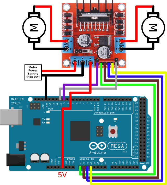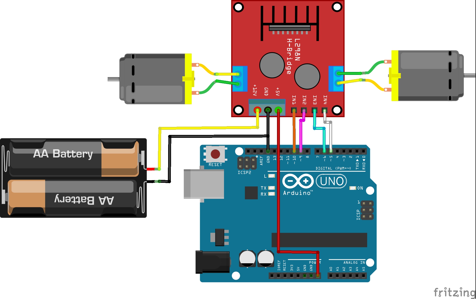


Take the water wheel analogy and think of the water hitting it in pulses but at a constant flow.

Motors are rated at certain voltages and can be damaged if the voltage is applied to heavily or if it is dropped quickly to slow the motor down. The voltage would be the water flowing over the wheel at a constant rate, the more water flowing the higher the voltage.

In motors try to imagine the brush as a water wheel and electrons as the flowing droplets of water. Pulse Width Modulation is a means of controlling the duration of an electronic pulse. Perfect for driving DC and Stepper motors for micro mouse, line following robots, robot arms, etc.Īn H-Bridge is a circuit that can drive a current in either polarity and be controlled by Pulse Width Modulation (PWM). This motor driver is perfect for robotics and mechatronics projects and perfect for controlling motors from microcontrollers, switches, relays, etc. It can control up to 4 DC motors, or 2 DC motors with directional and speed control It uses the popular L298 motor driver IC and has the onboard 5V regulator which it can supply to an external circuit.
Dimensions (approx): 43mm x 43mm x 27mm LxWxH (1.7″ x 1.7″ x 1.This L298 Based Motor Driver Module is a high power motor driver perfect for driving DC Motors and Stepper Motors. Control signal input voltage range: 4.5-5.5V high 0V low. When enabled, the 5V is available as an output on the power connector Logic power supply range Vss : +4V to +5.5V DC (Not required when internal regulator is enabled. Drive Voltage: +5V to +35V (Input voltage must be at least 6V when internal 5V regulator is enabled). Driver chip: L298N dual H-bridge driver. When disabled, a separate 5V input provides in order to control the logic level circuitry of this module. (When enabled, the module input voltage must be at least 6V). When enabled by the jumper, the 5V is provided as an output on the power connector, and can be used as a 5V DC supply for your other circuit components. The module includes an onboard 5V regulator. For example for motor A, a HIGH to IN1 and a LOW to IN2 will cause it to turn in one direction, and a LOW and HIGH will cause it to turn in the other direction. The motor direction is controlled by sending a HIGH or LOW signal to the drive for each motor (or channel). Two enable inputs are provided to enable or disable the device independently of the input signals. It can be used for other projects such as driving the brightness of certain lighting projects such as high powered LED arrays using Pulse Width Modulation (PWM) control. It can easily control the DC motor speed and direction, and can also control 2-phase stepper motors. This L298N-based driver module is a high voltage, high current dual full-bridge driver designed to accept standard TTL logic levels and drive inductive loads such as relays, solenoids, DC and stepping motors from 5V to 35V.


 0 kommentar(er)
